Building a Visual-Inertial-GNSS Acquisition System for High-Precision Global Localization
This summer, I had the opportunity to complete my Master 2 Data & AI internship at GEOBSYS, in collaboration with the IGN-LASTIG Laboratory. My project revolved around one of the most fundamental problems in robotics: global localization — the ability of a system to know where it is in the world.
This is the story of how I built a Visual-Inertial-GNSS acquisition system—from assembling the hardware to implementing synchronization and sensor fusion with OpenVINS.
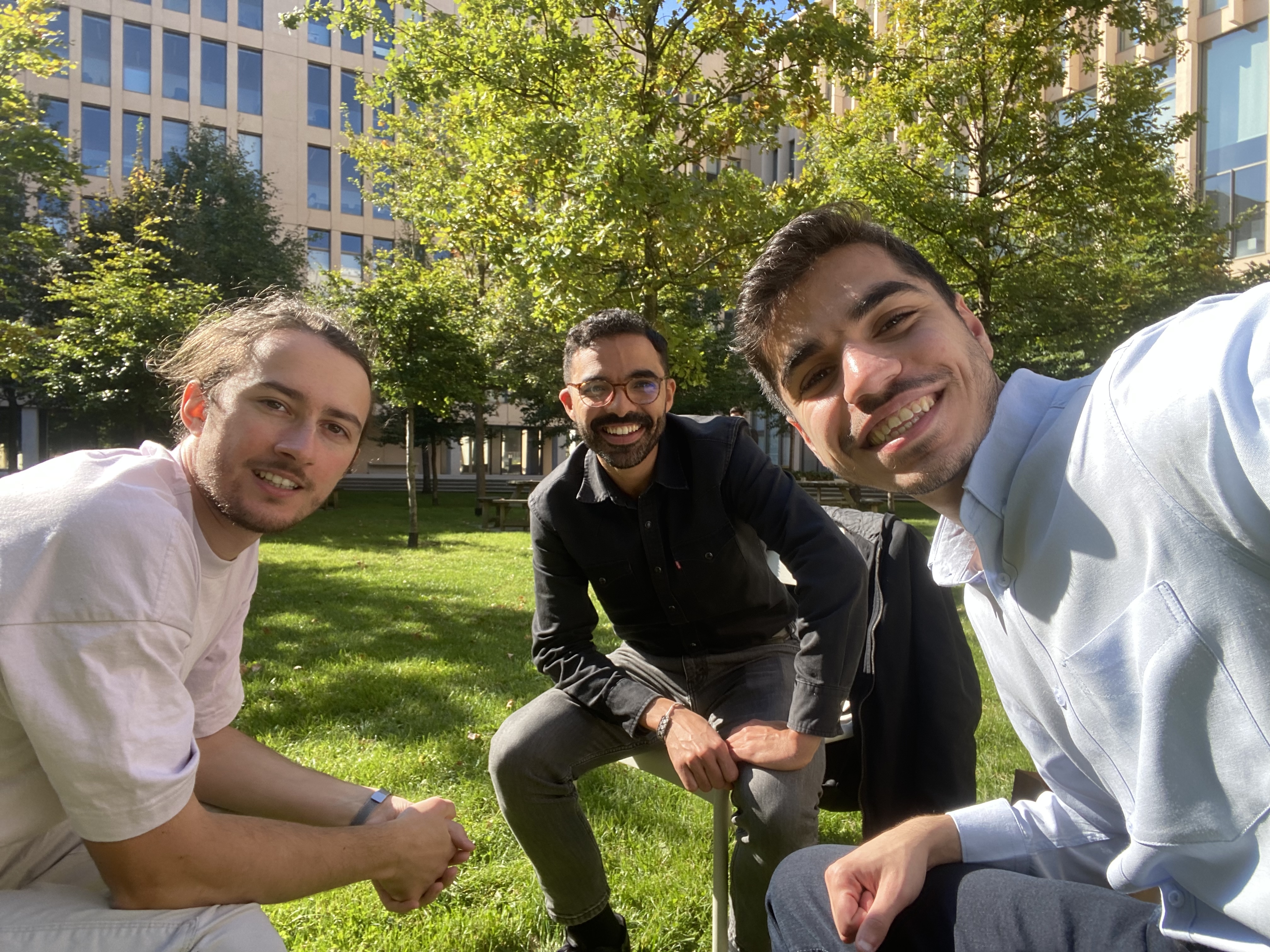
Gwennaël Guichard (GEOBSYS), Mehdi Daakir (LASTIG), and me =)
Why Global Localization Matters
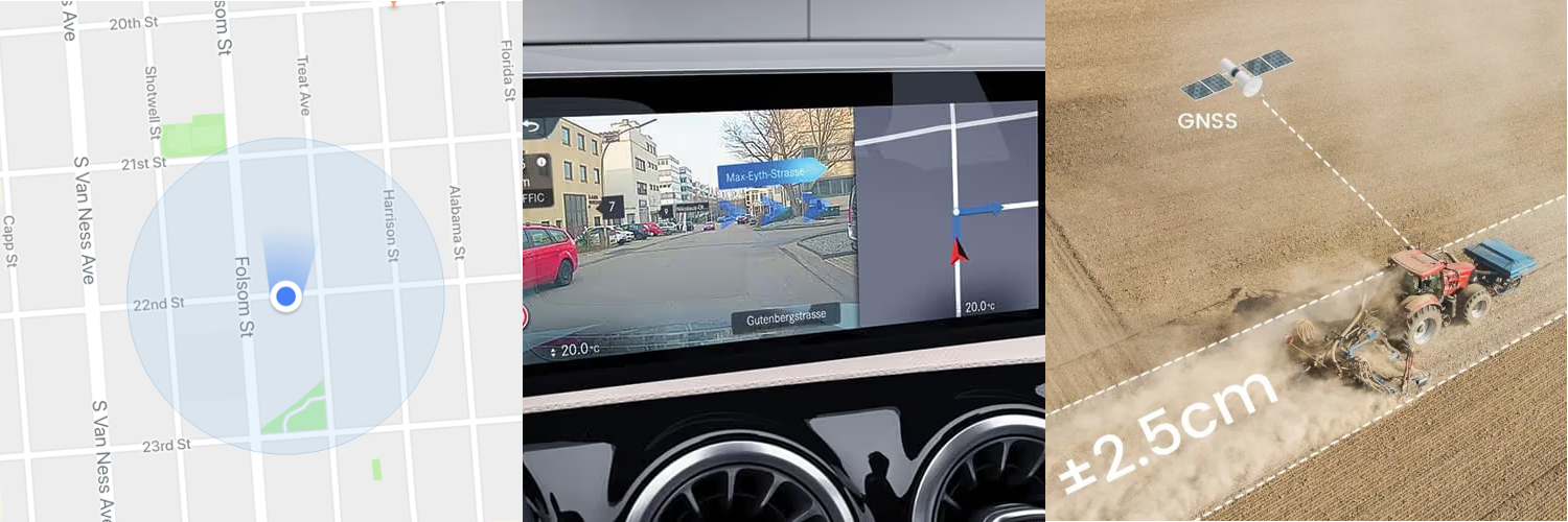
Global localization is everywhere — from autonomous vehicles and mobile mapping to precision agriculture. It’s what lets a self-driving car stay in its lane or a drone follow a pre-defined route.
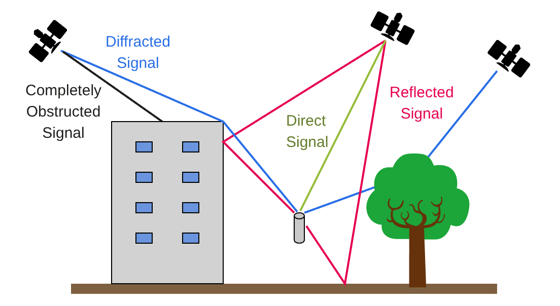
But GNSS-only systems face serious limitations:
- Weak or lost signals in obstructed areas!
- Multipath errors caused by reflections
- Lack of orientation (GNSS gives position, not attitude)
That’s where sensor fusion comes in. By combining GNSS with visual odometry and inertial measurements, we can compensate for each sensor’s weaknesses. Visual sensors capture rich environmental features, while IMUs provide high-frequency motion estimates, and GNSS anchors everything globally.
Building the Hardware Platform
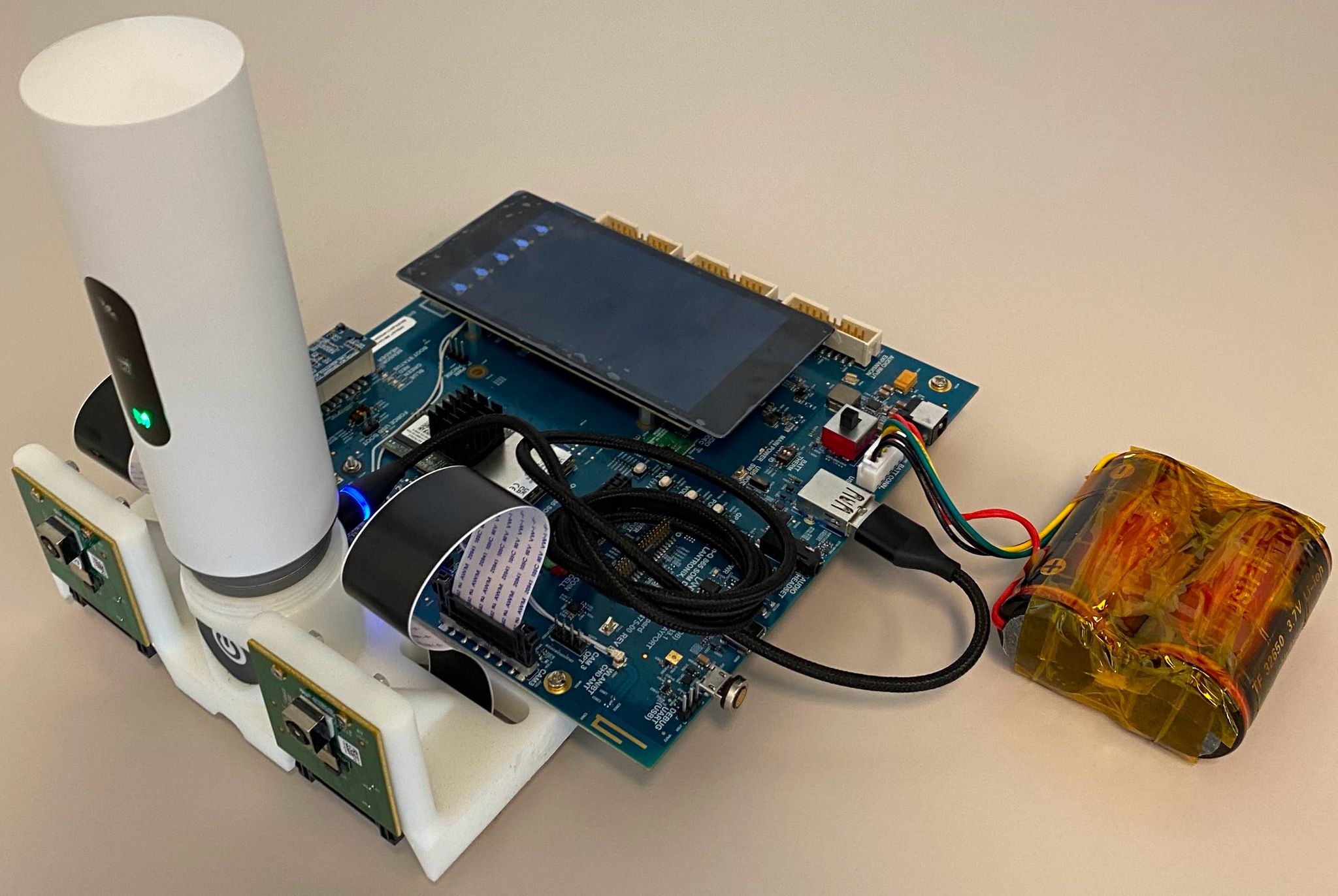
The system’s efficacy is fundamentally dependent on its hardware components and their precise integration. The architecture was designed around a central processing unit and a suite of complementary sensors.
Processing Unit: A Qualcomm Open-Q™ 865 Development Kit served as the central processing platform, equipped with an Open-Q 5165RB System-on-Module (SoM). Its multiple MIPI CSI interfaces and general-purpose I/O were critical for sensor integration.
Visual Sensors: A configurable stereo camera pair was formed using two independent Sony IMX258 camera modules. These rolling shutter sensors provide 13-megapixel resolution and support frame rates up to 30 fps at 4K resolution.
Inertial and GNSS Sensors: The GEOSTIX-F9, a high-precision, multi-frequency GNSS receiver, provided the system’s absolute position. Crucially, this module also integrates a high-performance LSM6DSV16X 6-axis Inertial Measurement Unit (IMU), which supplies high-frequency linear acceleration and angular velocity data.
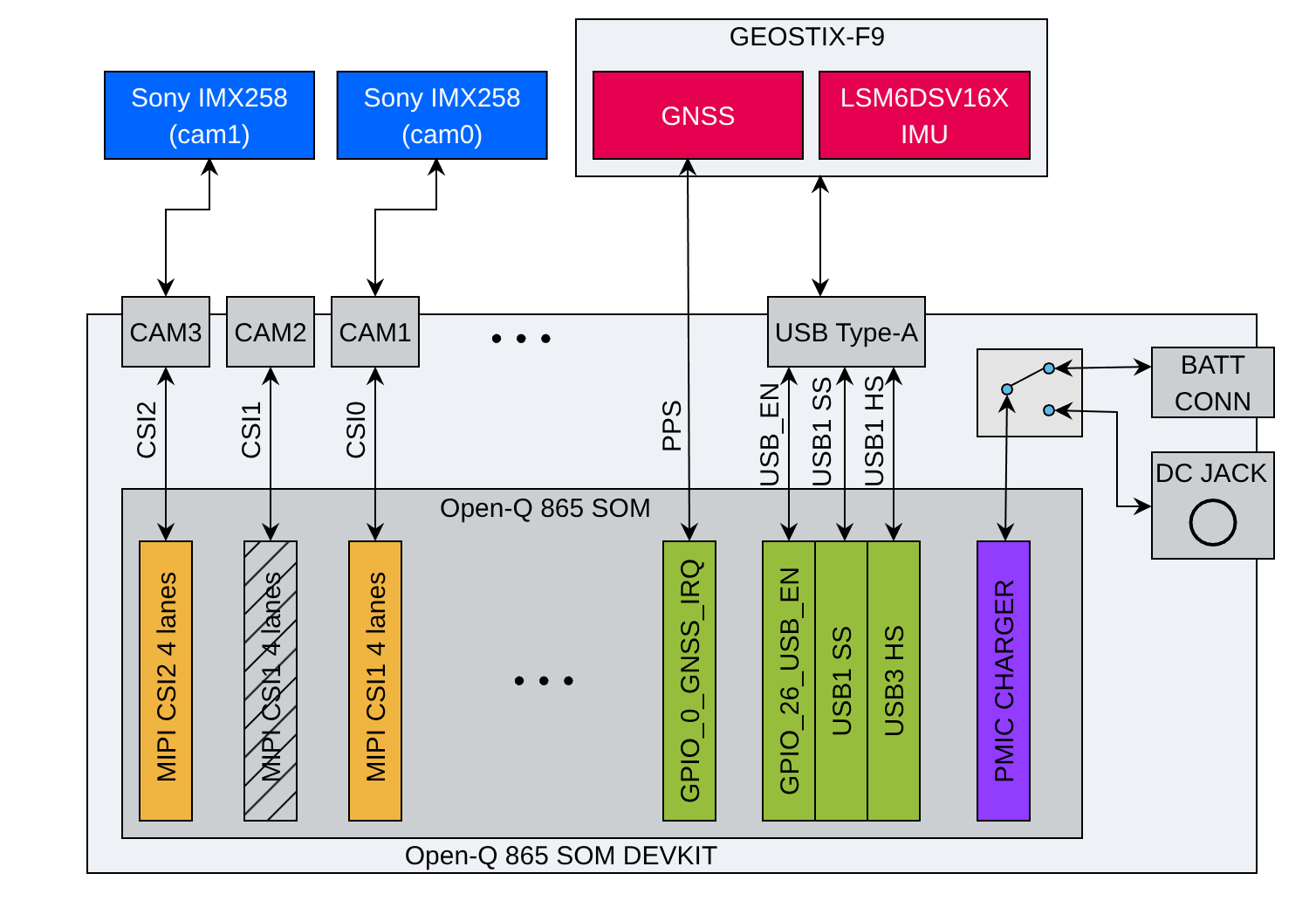
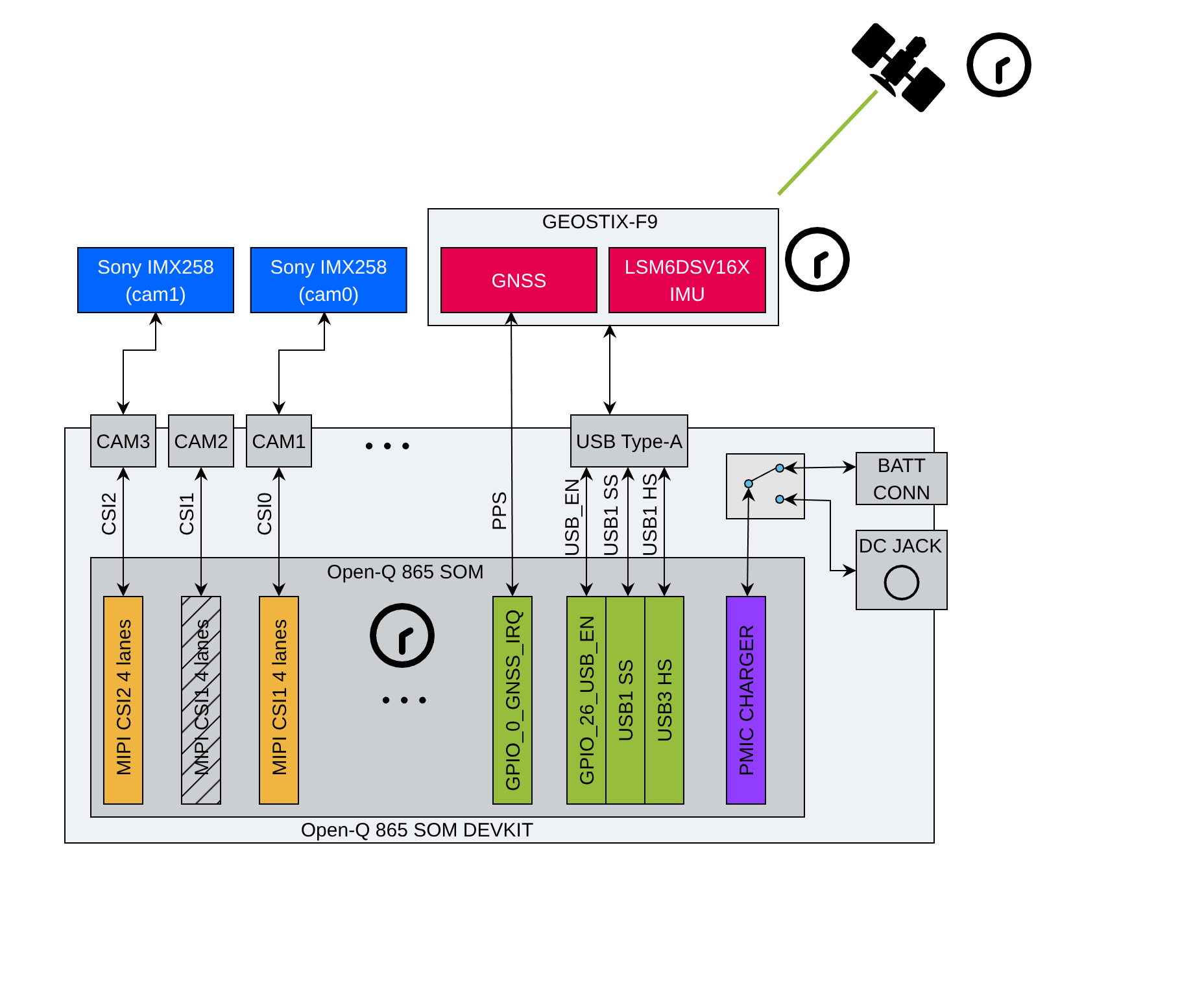
The hardware block diagram, illustrating the data pathways between the sensor suite and the processing board.
Synchronization: The Invisible Challenge
If you’ve ever tried to fuse data from multiple sensors, you know that time synchronization is the silent killer of accuracy. Even a few milliseconds of misalignment can completely distort trajectory estimates.
When we build a high-precision localization system, we’re combining data from several different sensors—specifically, our stereo cameras, our Inertial Measurement Unit (IMU), and our GNSS receiver.
The fundamental problem is that each of these components runs on its own clock. The GNSS gets its time from satellites, the IMU has its own internal timestamp (from the GEOSTIX), and the cameras are timed by the main processing board.
So, what happens if these clocks aren’t perfectly aligned? Imagine our system is on a bicycle moving at an average speed of 5 m/s (about 18 km/h or 11 mph). If our camera timestamp is off by just one second from our GNSS timestamp, the system will incorrectly believe the picture was taken 5 meters away from its actual location!
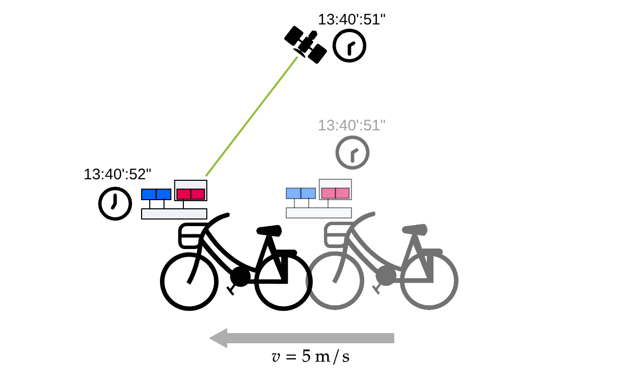
For our system to be accurate, we need to get this synchronization error down to around 0.1 milliseconds.
How do we fix this? We need one single, ultra-precise “source of truth” for time, and what’s better than the global clock from the GNSS satellites? Our GNSS receiver generates a special signal called PPS (Pulse Per Second). This signal is:
- Perfectly synchronized with the GNSS satellites.
- Accurate down to the microsecond or even nanosecond level.
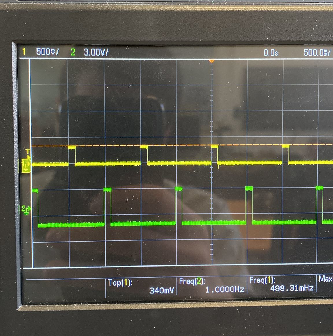
PPS signal (green) from GEOSTIX and a generated pulse signal (yellow) shown on an oscillocoscope
We feed this PPS signal directly from the GNSS receiver into our main processing board. This pulse acts as a “heartbeat” for our entire system, allowing us to align every single camera frame and IMU reading to a precise, unified global clock.
I integrated the PPS signal from the GEOSTIX into the Qualcomm board by modifying the Linux kernel device tree. Using GPSd and Chrony, I synchronized the system clock with sub-millisecond precision.
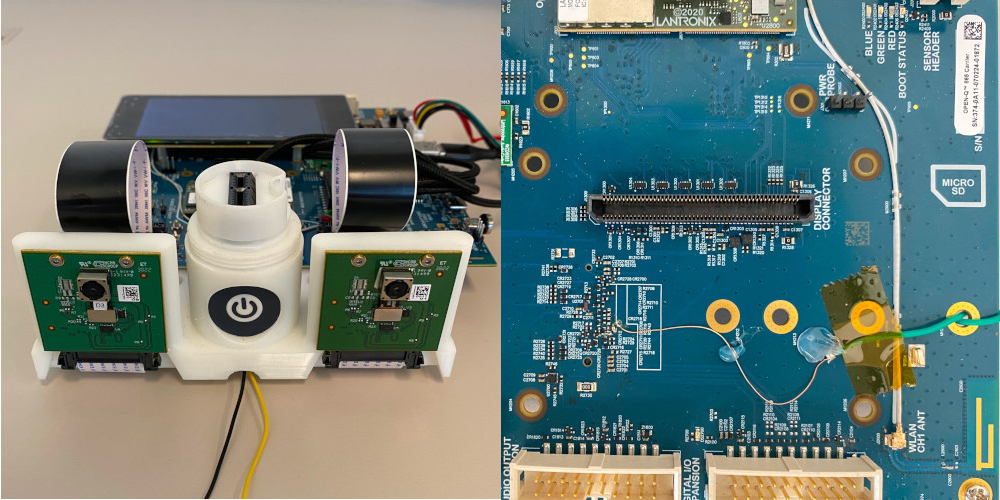
PPS signal from GEOSTIX (green wire) connected to GPIO0 using a pull-down resistor with 36-pin connector for the GEOSTIX
To enable hardware PPS on GPIO0, I patched the Qualcomm BSP and rebuilt the kernel. First, I added PPS support to the kernel configuration:
# poky/meta-qti-bsp/recipes-kernel/linux-msm/files/pps.cfg
CONFIG_PPS=y
CONFIG_PPS_CLIENT_KTIMER=y
CONFIG_PPS_CLIENT_LDISC=y
CONFIG_PPS_CLIENT_GPIO=y
Then I updated the BitBake recipe to apply this configuration:
# poky/meta-qti-bsp/recipes-kernel/linux-msm/linux-msm_5.4.bbappend
FILESEXTRAPATHS_prepend := "${THISDIR}/files:"
SRC_URI += "file://pps.cfg"
Finally, I modified the device tree to expose GPIO0 as a PPS source:
&soc {
    pps_gpio: pps-gpio {
        compatible = "pps-gpio";
        gpios = <&tlmm 0 GPIO_ACTIVE_HIGH>;
        pinctrl-names = "default";
        pinctrl-0 = <&pps_gpio_pins>;
        status = "okay";
    };
};


&tlmm {
    pps_gpio_pins: pps_gpio_pins {
        mux {
            pins = "gpio0";
            function = "gpio";
        };
        config {
            pins = "gpio0";
            input-enable;
            bias-disable;
        };
    };
};
With this done, the PPS signal became available through /dev/pps0, allowing the GNSS receiver to discipline the system clock at the kernel level.
“We needed synchronization precision better than 0.1 ms. After firmware updates, kernel recompilation, and a few sleepless nights — we got it.”
Another synchronization challenge exists with the stereo cameras: frames must be captured almost simultaneously to ensure accurate depth reconstruction.
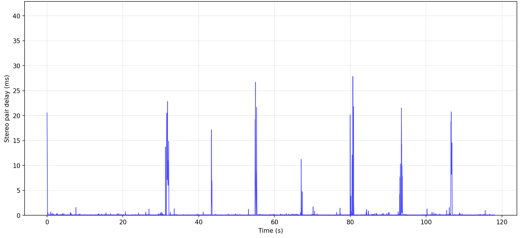
For the stereo cameras, I developed a multi-threaded GStreamer pipeline. After benchmarking several configurations, this one achieved a mean delay of 0.31 ms — good enough for robust stereo reconstruction.
30fps@2k over 120s → 7200 frames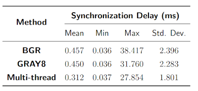
Calibrating the Sensors
Once the hardware was synchronized, I moved on to calibration — the process of teaching the system how its sensors “see” and “feel” the world.
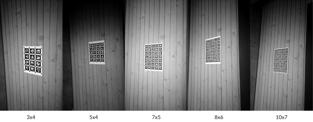
Using Kalibr and AprilTags, I computed the intrinsic and extrinsic camera parameters, estimated the IMU’s noise characteristics using Allan variance, and finally performed IMU–camera extrinsic calibration. The result was a fully calibrated stereo-IMU rig, ready for sensor fusion.
Sensor Fusion with OpenVINS
To process and fuse the multi-sensor data, I integrated everything into OpenVINS, an open-source visual-inertial odometry framework based on the Extended Kalman Filter (EKF).
OpenVINS estimates the system’s position, velocity, and orientation by continuously updating its belief with incoming visual and inertial data. I extended its architecture to incorporate GNSS measurements, allowing the system to correct for long-term drift and maintain global consistency.
In practice, the GNSS updates acted as “anchors” for the visual-inertial trajectory — stabilizing it over time and keeping it aligned with the real world.
Experiments and Results
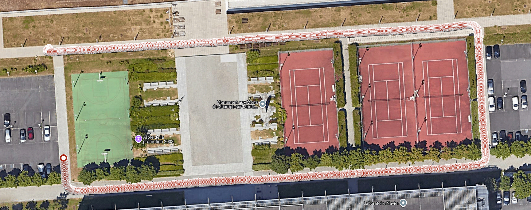
I tested the system in two real-world environments: Télécom Paris — an open, urban environment with partial GNSS visibility.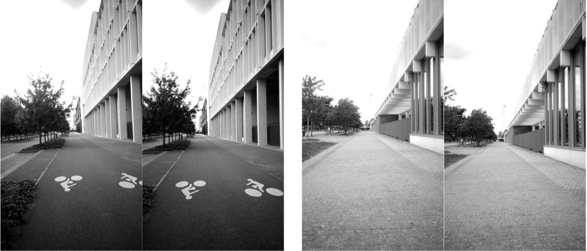
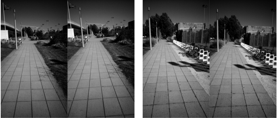
ENPC — a semi-structured outdoor scene ideal for evaluating multi-sensor synchronization.
The system successfully produced globally consistent trajectories, with smooth transitions between visual-inertial and GNSS-dominant regions.